Introduction
My journey started with simple SDR experiments with Reverse engineering a digital radio signal, but I wanted more.
I wanted to be able to decode real-world signals! So I stood up from my chair and started looking around my house.
Soon I found two interesting items:
- The gas meter, which has a pretty nice label with
169MHzwritten on it.

- The heat allocators on the radiators, which are not labeled with a frequency, but must communicate somehow, so I guess they also use radio signals.

Although I really wanted to go straight to the radio signals, I decided to approach them step by step, so I started searching for documentation.
Wireless M-Bus
Starting point
As soon as I started researching, I found out that most of the meters in the world (and especially in Europe) use a protocol called Wireless M-Bus (or WMBus) to communicate their readings.
Wireless M-Bus is a wireless extension of the already existing M-Bus (Meter-Bus) protocol, which is a European standard (EN 13757-2 and EN 13757-3) for reading water, gas, heat, and electricity meters using a wired connection.
But where should I start? I needed a real signal to analyze. I tried to capture some signals with my RTL-SDR, but I had no idea what to look for, and so I eventually gave up.
Instead, after digging deeper into the internet, I discovered several useful resources.
First of all I discovered that:
I needed Mode N, because it is the only one used for the 169MHz frequency band.
Useful resources
First of all, the classic rtl_433 has partial Wireless M-Bus support. However, it only supports a few modes, and mode N is not one of them.
Then I stumbled upon rtl_wmbus, a tool specifically designed to decode Wireless M-Bus signals captured with RTL-SDR or RTL433. However, again, it only supported a few modes, and mode N was not one of them.
However, I found a particularly interesting GitHub issue in that repository, where contributors were discussing adding Wireless M-Bus Mode N support.
The interesting part was that @optiluca had already uploaded some sample captures of Wireless M-Bus signals and had given the link to download those captures!
As such, I downloaded the sample captures right away and started analyzing them.
Analyzing the captures
Even though the captures were not recorded by me, they were still a great starting point.
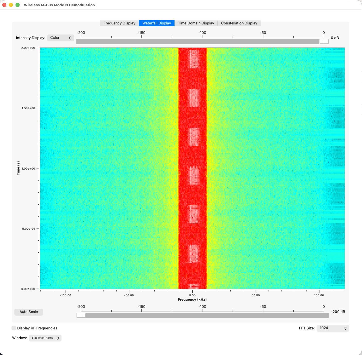
I already had the I/Q Quicklook by triq.org installed, so I chose a nice looking capture by looking at the waterfall, and opened it.
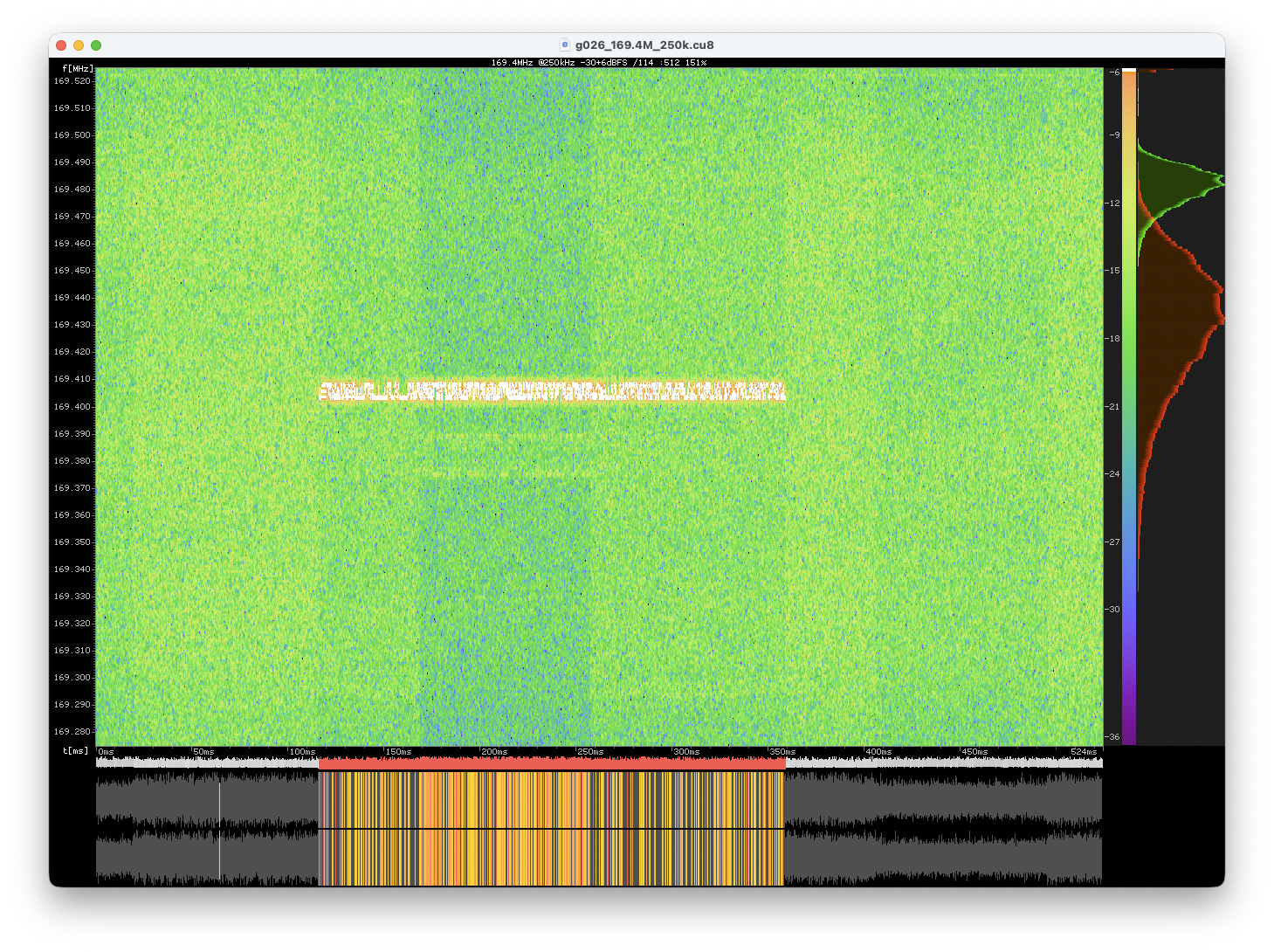
You can clearly see that the signal oscillates between two frequencies, which is a strong hint that the modulation used is Frequency Shift Keying (FSK), in this case 2-FSK.
URH
I loaded the capture in URH, set the modulation, and started decoding the signal.
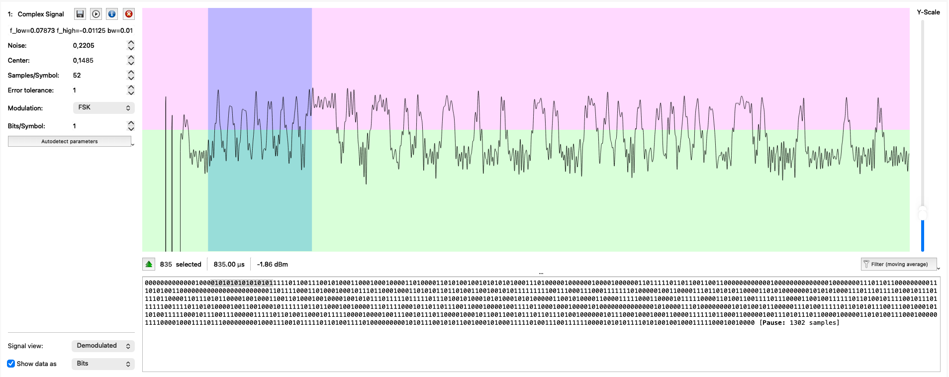
I started manually decoding the bits in a simple file, but after an enormous amount of effort (weeks passed) I was not satisfied with the manual decoding; there clearly were strange values for simple fields: I was struggling a lot.
So I started experimenting with other tools. In particular, with GNU Radio.
GNU Radio
Building a GNU Radio flowgraph was insane to me; I had never experienced such frustration before. Luckily for me, nowadays LLMs are available, so I used one to help me build the flowgraph. Of course it hallucinated many times, but at least it gave me a starting point.
So, first of all, I built a simple flowgraph to convert the .cu8 file to a complex signal:
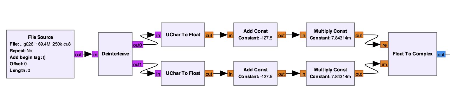
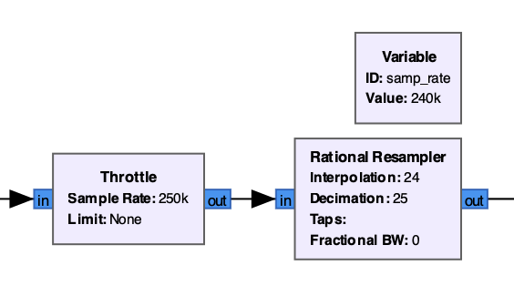
Then, I just added some normalization to help me with the playground. The throttle block allowed me to slow down the playback speed so that I could visualize parts of the signal more easily when I needed to. The resampling was just to use a sample rate that was a multiple of the baud rate.
Then, I centered the signal around 0 and applied a low-pass filter to remove the noise:
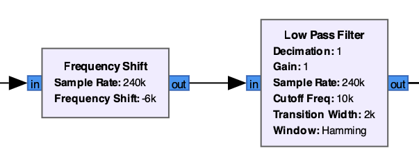
And confirmed that the result was good with a QT GUI Sink block:
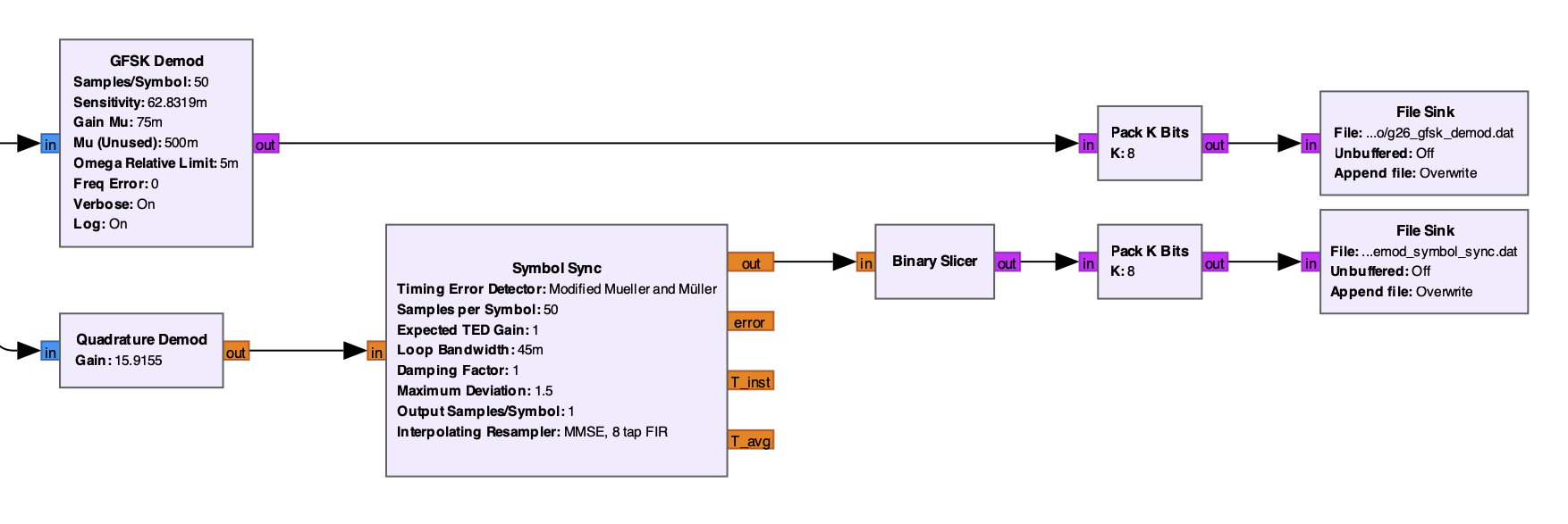
After that I tried and retried a lot. I think I created and deleted hundreds of blocks just to finally arrive at a working flowgraph. Then, finally, I kept two different working flowgraphs, that I can tweak in similar but different ways.
The first one is simpler; it just uses a built-in GFSK Demod block. The second one uses a Quadrature Demod block followed by a Symbol Sync block and a Binary Slicer block. Both do the same thing, but in different ways: the GFSK Demod block sensitivity (2 * math.pi * fsk_deviation_hz / samp_rate) is the inverse of the Quadrature Demod gain (samp_rate / (2*math.pi*fsk_deviation_hz)).
Here is the full flowgraph:
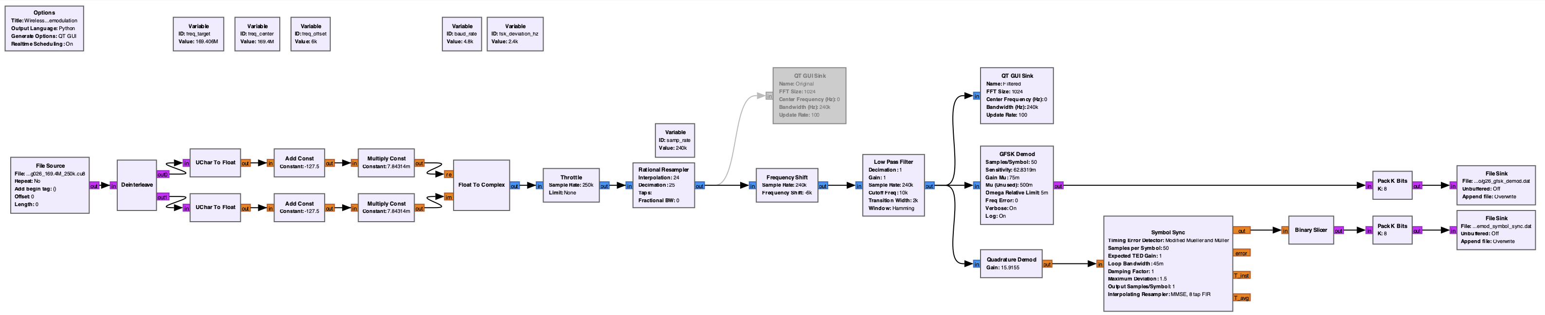
Downloadable here (right click, save link as): wmbus-mode-n.grc
The flowgraph, when run, produces two files that should contain almost the same bitstream.
To decode Wireless M-Bus frames from the bitstream, I used a simple Python script, that you can find below:
decode-wmbus.py (Click to expand)# decode-wmbus.py
from struct import unpack
def crc16_en13757_bytes(data):
POLY = 0x3D65
INIT = 0x0000
XOROUT = 0xFFFF
crc = INIT
for byte in data:
for i in range(8):
bit = (byte >> (7 - i)) & 1
c15 = (crc >> 15) & 1
crc = ((crc << 1) & 0xFFFF)
if c15 ^ bit:
crc ^= POLY
return crc ^ XOROUT
files = [
'g26_gfsk_demod.dat',
'g26_quad_demod_symbol_sync.dat'
]
for f in files:
print(f"\n\nFile: {f}")
# Original bits array from file
o_bits = [(byte >> (7 - i)) & 1 for byte in open(f, 'rb').read() for i in range(8)]
# Search for preamble and sync
preambles_indices = []
preamble = [0,1]*8
sync1 = [1,1,1,1,0,1,1,0]
preamble_plus_sync1 = preamble + sync1
for i in range(len(o_bits) - len(preamble_plus_sync1)):
if o_bits[i:i+len(preamble_plus_sync1)] == preamble_plus_sync1:
preambles_indices.append(i)
print(f"Preamble found at bit position: {i}")
print(f"Total preambles found: {len(preambles_indices)}")
if not preambles_indices:
print("No preamble found.")
continue
for preamble_index in preambles_indices:
# Re-align data to preamble_index % 8
aligned_bits = o_bits[preamble_index:]
data = bytes(
sum(bit << (7 - i) for i, bit in enumerate(chunk))
for chunk in [aligned_bits[i:i+8] for i in range(0, len(aligned_bits), 8)]
if len(chunk) == 8
)
print(f"Realigned data (length {len(data)} bytes): {data.hex()}")
# L1 sync
preamble = unpack('>H', data[0:2])[0]
sync = unpack('>H', data[2:4])[0]
# L2 fields
L_field = unpack('>B', data[4:5])[0]
C_field = unpack('>B', data[5:6])[0]
M_field = unpack('>H', data[6:8])[0]
A1_field = unpack('>I', data[8:12])[0]
A2_field = unpack('>H', data[12:14])[0]
# decode M field
alphabet = "_ABCDEFGHIJKLMNOPQRSTUVWXYZ+-*/"
M_third_letter = alphabet[(M_field & 0b11111)]
M_second_letter = alphabet[(M_field >> 5) & 0b11111]
M_first_letter = alphabet[(M_field >> 10) & 0b11111]
M_top_bit = (M_field >> 15) & 0b1
# decode A field
A_device_type = A2_field & 0xFF
A_version = (A2_field >> 8) & 0xFF
A_id = A1_field
print(f"At preamble index {preamble_index}:")
print(f" Preamble: 0x{preamble:04X}")
print(f" Sync: 0x{sync:02X}")
print(f" L field: 0x{L_field:02X} (length = {L_field} bytes)")
print(f" C field: 0x{C_field:02X}")
print(f" M field: 0x{M_field:04X} ({M_first_letter}{M_second_letter}{M_third_letter}, top bit: {M_top_bit})")
print(f" A field: 0x{A1_field:08X}{A2_field:04X} (ID: 0x{A_id:04X}, Version: 0x{A_version:02X}, Device Type: 0x{A_device_type:02X})")
print()
format = None
if sync == 0b11110110_10001101:
format = "A"
elif sync == 0b11110110_01110010:
format = "B"
else:
print(f"Unknown mode/format {sync:04X}")
continue
L7_data = bytes()
print(f"Mode N, Format {format}")
if format == "A":
CRC_field = unpack('>H', data[14:16])[0]
actual_crc = crc16_en13757_bytes(data[4:14])
print(f" CRC field: 0x{CRC_field:04X}")
if actual_crc == CRC_field:
print(f" CRC valid: 0x{CRC_field:04X}")
else:
print(" " + "-"*8 + f"> CRC invalid! Computed: 0x{actual_crc:04X}, Expected: 0x{CRC_field:04X}")
# ...
# TODO
# ...
elif format == "B":
CI_field = unpack('>B', data[14:15])[0]
print(f" CI field: {CI_field:02X}")
length = min(128, L_field) - 13
print(f" DATA field length: {length} bytes")
DATA_field = data[15:15+length]
L7_data += DATA_field
CRC_field = unpack('>H', data[15+length:15+length+2])[0]
actual_crc = crc16_en13757_bytes(data[4:15+length])
print(f" DATA field: {DATA_field.hex()}")
if actual_crc == CRC_field:
print(f" CRC valid: 0x{CRC_field:04X}")
else:
print(" " + "-"*8 + f"> CRC invalid! Computed: 0x{actual_crc:04X}, Expected: 0x{CRC_field:04X} <" + "-"*8)
# If L_field is greater than 128, then there is another optional frame
if L_field > length:
OPT_DATA_field = data[15+length+2:15+length+2+L_field-129]
L7_data += OPT_DATA_field
OPT_CRC_field = unpack('>H', data[15+length+2+L_field-129:15+length+2+L_field-129+2])[0]
actual_opt_crc = crc16_en13757_bytes(OPT_DATA_field)
print(f" OPT DATA field: {OPT_DATA_field.hex()}")
if actual_opt_crc == OPT_CRC_field:
print(f" OPT CRC valid: 0x{OPT_CRC_field:04X}")
else:
print(" " + "-"*8 + f"> OPT CRC invalid! Computed: 0x{actual_opt_crc:04X}, Expected: 0x{OPT_CRC_field:04X} <" + "-"*8)
print(f"\nLayer 7 data: {L7_data.hex()}")
This script allowed me to programmatically decode the bitstreams into the following (I stripped one of the two almost identical outputs for brevity):
Preamble found at bit position: 563
Total preambles found: 1
Realigned data (length 243 bytes): 5555f6728c4434352554741021037db33000800101db00753000001bc688bb11ab6992bfe71c7f4130ed586a02a8eef4bbd86eb0919a242577df74a2a2a0ca187c617c34cf70c9fb4bcbbf3da84c8bf6c48778b6e6213d8885020143a0152c1d3ed5ce45a7c5ce0fb4c5f084e5d8459976e902e2230fd8c13aec20d4e20f08f7022397da7a00ae56451f4e7e157a923e241007e535b071678cc024d505a2a1135bd95326c7f0023584579cd8147359db8996218f38e8258f9ee098dcb8850ec982a25491e404b1e4e915af725c0514513c50d7749d4ba117caa0bb70183209a51ec8134decafeb8498630c06ce686f8949e633
At preamble index 563:
  Preamble: 0x5555
  Sync: 0xF672
  L field: 0x8C (length = 140 bytes)
  C field: 0x44
  M field: 0x3435 (MAU, top bit: 0)
  A field: 0x255474102103 (ID: 0x25547410, Version: 0x21, Device Type: 0x03)

Mode N, Format B
  CI field: 7D
  DATA field length: 115 bytes
  DATA field: b33000800101db00753000001bc688bb11ab6992bfe71c7f4130ed586a02a8eef4bbd86eb0919a242577df74a2a2a0ca187c617c34cf70c9fb4bcbbf3da84c8bf6c48778b6e6213d8885020143a0152c1d3ed5ce45a7c5ce0fb4c5f084e5d8459976e902e2230fd8c13aec20d4e20f08f70223
  CRC valid: 0x97DA
  OPT DATA field: 7a00ae56451f4e7e157a92
  OPT CRC valid: 0x3E24

Layer 7 data: b33000800101db00753000001bc688bb11ab6992bfe71c7f4130ed586a02a8eef4bbd86eb0919a242577df74a2a2a0ca187c617c34cf70c9fb4bcbbf3da84c8bf6c48778b6e6213d8885020143a0152c1d3ed5ce45a7c5ce0fb4c5f084e5d8459976e902e2230fd8c13aec20d4e20f08f702237a00ae56451f4e7e157a92
And with that, I was finally able to decode Wireless M-Bus Mode N signals!
Interpreting the Layer 7 data is another story, but at least I managed to get this far.